Frequency inverter: all information about the device
Table of contents
- The physical basis of frequency converters
- Design and operation of frequency converters
- Rectifier
- Intermediate chain
- Inverter
- Types of frequency converter control
- Frequency converter interfaces
- The benefits of using frequency converters
- Disadvantages of frequency converters
- Purpose and application of frequency converters
- How to choose a frequency converter?
- How is the frequency converter connected?
- Safety precautions for wiring the frequency converter
- Recommendations for purchasing frequency converters

The physical basis of frequency converters
The theoretical basis for the operation of frequency converters was outlined as early as the 1930s, but at that time, due to the lack of transistors and microprocessors, practical implementation was not possible. Only when the USA, Europe and Japan developed the missing components did the first variations of frequency converters start to appear. Since then, they have undergone significant technological changes, but their operating principle is still based on the same physical laws.
The operation of frequency converters is based on the following formula:

From this expression it is immediately clear that if the frequency of the input voltage changes, which in the formula is designated as f1, the angular velocity of the stator's magnetic field will also change, which determines the rotational speed of the stator itself. This effect can only be achieved if the p-value (number of pole pairs) remains constant.
So what does this give us? Firstly, the ability to continuously adjust the speed. This is especially relevant at start-up peaks. Secondly, this dependence makes it possible to increase the slip of the asynchronous motor, increasing its efficiency.
It is also worth noting that characteristics such as power factor, efficiency, overload capacity factor take high values precisely with simultaneous frequency and current voltage control. The patterns of change in these parameters are directly dependent on the load torque, which can take on the following characteristic:
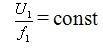
- constant. With this type of load torque, the stator voltage will be directly proportional to the frequency:
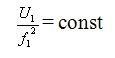
- fan. In this case, the voltage will be proportional to the frequency squared:
- inversely proportional. In this case, the formula will look like this:

Design and operation of frequency converters
When looking at the overall design of frequency converters, it is worth highlighting two main blocks of components:
- management;
- electrical transformations.
The first unit is usually represented by a microprocessor, which receives commands from external control systems and interfaces and transmits them directly to the electric converter elements.
The Power Conversion Unit is the main operating mechanism of the entire system. It is responsible for accepting the input current and converting it to the desired values set by the operator via the control unit. This unit consists of the following elements:
- rectifier;
- intermediate chain;
- inverter.
Let's talk about each one in more detail.
Rectifier
This component is designed to generate pulsating voltages in single- or three-phase AC networks. Rectifiers are usually built with either diodes or thyristors. In the former case, they are considered uncontrolled and in the latter they are controlled.
- uncontrolled rectifiers. These use two groups of diodes which are connected to different terminals and conduct different voltages - positive and negative. Ultimately the output voltage is equal to the difference of the voltages across these diode groups and in mathematical terms has the following value: 1.35* mains input voltage.
- controlled rectifiers. These rectifiers are designed with thyristors instead of diodes. They can be supplied with an input signal a, which induces a current delay expressed in degrees. In cases where the value of this parameter varies from 0-90 degrees, thyristors play the role of rectifiers, and when it is 90-300 degrees, they play the role of inverters. The output value of DC voltage is: 1,35* mains input voltage*cos α.
Intermediate chain
The intermediate circuit acts as a kind of storage from which the motor receives its energy via the inverter. Depending on the combination of inverter and rectifier, the intermediate circuit can have one of the following formations:
- The power supply inverter. In this case, the intermediate circuit includes a powerful inductive coil which converts the rectifier voltage into a varying direct current. The motor voltage itself is determined by the load. This type of circuit can only work with controlled rectifiers.
- Inverters are voltage sources. In this case, a filter is used in the intermediate circuit, which includes a capacitor. It smooths out the voltage coming from the rectifier. These circuits are capable of working with any type of rectifier.
- Variable DC voltage circuit. In this case, a breaker is installed upstream of the filter, which has transistors that switch off and on the voltage supply from the rectifier. In this case, the filter ensures that the rectangular voltages after the chopper are smoothed and also maintains the DC voltage at a given frequency.
Inverter
The inverter is the last link in the frequency converter before the motor itself. It is the one that finally converts the voltage into the form required for operation. As a result of the conversions described above, the rectifier and the intermediate circuit are converted:
- constant current of a changing nature;
- a varying or unchanging DC voltage.
The inverter itself actually provides the voltage of the required frequency. If it is supplied with variable voltage or current, it generates only the desired frequency. If it is not changing, it generates both the desired frequency and the desired voltage.
Typically high-frequency transistors are used in inverter designs, with switching frequencies in the 300 to 20 kHz range.
Types of frequency converter control
There are two main methods of controlling electric motors using frequency converters:
- scalar;
- vector.
Asynchronous control systems are the most common by far. They are used in drives for fans, pumps, compressors etc. The basic principle behind scalar control is to change the frequency and voltage amplitude according to the law U/fn = const, where n is always greater than 1. Accordingly, by changing the voltage U, we change the frequency f to the power of n. The degree value is determined according to the characteristics of the frequency converter itself and its purpose.
The scalar control technique itself is quite simple in terms of technical implementation, but has two significant drawbacks. The first is that without an additional speed sensor you cannot regulate the shaft speed because it is directly dependent on the load. You can solve this problem by simply purchasing a sensor.
But there is another disadvantage - the inability to adjust torque. It would seem that this problem can also be solved by buying a torque sensor. But it is quite expensive and the control would be highly questionable. In addition, it is not possible to control speed and torque together with the scalar type of control.
Vector control implies that the system itself contains a mathematical model of the motor operation, which allows both speed and torque to be calculated at the software level using the input parameters. It is only necessary to have a sensor that reads the stator phase current.
There are two classes of vector control systems:
- without speed sensors;
- with speed sensors.
Their use in one application or another is determined by the operating conditions of the engine. If the shaft speed range does not exceed 1:100 and the accuracy requirement is less than 0.5%, then a system without encoders is fine.
If, however, the speed range is 1:1000 and accuracy requirements are set at up to 0.02%, then it is better to use sensor-based control systems.
It is worth noting that vector control also has its disadvantages. For example, they require a lot of computing power and knowledge of motor operating parameters. In addition, vector control cannot be used where more than one operating unit is connected to the frequency converter - scalar systems would be appropriate.
Frequency converter interfaces
Most modern frequency inverters are designed with a number of different interfaces that can be used to connect third-party equipment or synchronise several frequency inverters. Let's take a look at the main inputs and outputs used in such devices:
- analogue input. This interface is used to receive a standard analogue signal in the production range of 0(4) to 20 mA or 0 to 10V. The frequency inverter can be controlled via this input. For example, the minimum value of the analogue signal can signal to the device that the output frequency to the motor should have its minimum value and vice versa the maximum value should correspond to the maximum value;
- analogue output. This output is similar in function to the input. Only in this case, it transmits the frequency information to the motor via an analogue signal of a certain value, which allows the operating mode to be monitored;
- binary input. This input is capable of accepting bouncing signals. Like the analogue input, it is capable of changing parameters. For example, the minimum signal can correspond to the instantaneous minimum output frequency of the inverter, and the maximum signal can correspond to the maximum output frequency;
- discrete output. This output allows the same operations as the input, only in reverse order;
- RS-485. This interface is a full-fledged input that allows full communication with the frequency converter, e.g. via a computer. It can be used to configure the operating parameters of the equipment, monitor its status, etc. The RS-485 interface uses a special differential signal, which allows for a line length of up to 120 metres. In this way it is possible to install the frequency converter in the production area and to control it in the control room, remote from the workspace.
In addition, other interfaces can be used in frequency inverters. It all depends on the specific device model and manufacturer.
The benefits of using frequency converters
Frequency inverters have found wide application in a wide variety of production niches and equipment. The high demand for these devices is due to the following advantages of their use:
- reduced starting current. When starting a motor using direct starters, there is a sharp increase in current, with values 7-15 times higher than the nominal current. This has a negative effect on the drive and can lead to insulation breakdown, burnout of contacts and a number of other negative effects. In addition, the mechanical components of the system are also affected by this method of starting. During start-up, the motor components are subjected to high loads, which leads to faster wear and tear. Frequency converters can significantly reduce the starting loads on the motor, prolonging its maintenance-free lifetime;
- profitability. As a rule, motors that support ventilation and pumping systems always run at the same frequency, and pressure and other operating parameters are adjusted by means of valves (dampers, dampers, etc.). This leads to wasteful use of energy. If frequency converters are used, it is possible to adjust the system's operating parameters by adjusting the motor's intensity. This makes it possible to use its resources more rationally;
- increased adaptability. With frequency inverters, it is possible to design automated systems that will adjust the operation of equipment according to set algorithms. This reduces the labour costs of production processes and makes them more precise by eliminating the human factor;
- maintainability. If a frequency converter breaks down, you can take it to a workshop where a technician will replace the defective parts. However, this only applies to the electrical converter unit - the control units are much more complex and more demanding to repair.
Frequency inverters are the optimum solution for a wide variety of production processes and for debugging work equipment that uses electric motors.
Disadvantages of frequency converters
Frequency converters also have their own disadvantages. In fact, they are:
- expensive. Frequency inverters are the most expensive inverter equipment. However, this disadvantage is very relative, considering that such devices can extend the life of electric motors as well as increase their maintenance-free operation;
- limited. Not all older motors are capable of operating in conjunction with a frequency converter. Even if it is technically possible, the operating life of older models may simply not be sufficient for constant frequency and shaft speed fluctuations;
- difficult to set up and connect. A frequency converter is difficult to install by yourself, so it is often necessary to outsource this work, which in turn entails a certain financial cost.
If you compare the disadvantages and advantages of frequency converters, they still look more efficient even when compared to other converters. This is what makes them particularly popular in manufacturing industries, where they are used almost everywhere.
Purpose and application of frequency converters
Frequency converters have been used in the construction of electromechanical devices and units for many years. They allow the modulation of the current frequency, which in turn makes it possible to precisely regulate the speed of the motor. Today, frequency inverters are used in many industries. We will look at just a few of them:
- Food industry. Frequency converters are often used to adjust the operation of filling lines. They make it possible to adjust the product feed and belt speed to the capacity of the packaging machine itself. In addition, they are often used in large mixer units, ventilation systems, etc.
- Mechanisation of production equipment. Conveyor belts, painting and washing machines, presses, stamping machines, etc. are all in need of frequency converters. These devices make it possible to control the speed of work processes, reducing the likelihood of product damage and improving the quality of the end result.
- Medicine. The highest technical standards are always expected of all medical equipment which cannot be fulfilled without the use of controlled motors in conjunction with frequency inverters. They are installed in various life-support systems, bed lifts, etc.
- Lifting and conveyor technology. Lifts, cranes, hoists - all of which have long made use of frequency converters. They enable precise control of the speed of various operations as well as prolonging the maintenance-free operation of the equipment.
The list of applications for frequency inverters is endless, since they can be used in any equipment that uses electric motors.
How to choose a frequency converter?
There are several key parameters to consider when selecting a frequency converter:
- Power output. This parameter of the frequency converter must be matched to the power of the motor with which it will be used. Choose a device whose power rating corresponds to the rated current. Buying a frequency converter with very high specifications is simply pointless, because it will cost much more, and there may be problems with adjustment.
- Type of load. The type of load depends on how the machine to which the frequency converter will be connected is operated. In fan loads, for example, there are no overloads, but in the case of a press, the current can exceed the rated values by 60 percent or more. Accordingly, this must be taken into account in the selection and a certain amount of "travel" must be left.
- Type of engine cooling. Engines can be equipped with forced cooling systems or self-cooling. In the second case, special blades are attached to the rotor impeller, which rotate with the rotor and blow on the engine. Accordingly, the normal blowing action in this case depends directly on the rotational speed. If the motor is operated at a reduced speed for a longer period, overheating may occur. Accordingly, it is better to take care of additional cooling if the frequency variation is greater than 10% of the nominal value.
- Input voltage. This determines at what voltage the frequency converter is able to operate. It is not enough to know that the mains voltage is usually around 380 V. Often, surges in the +-30% range occur. In addition, surges of 1 kV often occur in networks with a large amount of power equipment. Accordingly, the wider the operating voltage range of the frequency converter, the more reliable it will be.
- Braking method. The motor can be stopped either by inverter bridge or electrodynamic braking. The former method is more suitable for precise and fast braking, while the latter is suitable for machines with frequent braking or where gradual stopping is necessary. It is essential to pay attention to this.
- Environment and protection. The frequency converter data sheet usually indicates the environment in which the unit is to be used. For example, moisture-proof models meet the IP 54 standard - they are resistant to moisture and can be used in rooms with vapour vapour and high humidity.
- Type of control and interfaces. It is essential to pay attention to the availability of suitable connectors for connection as well as board options - some models are designed for on-site installation and others in a separate control cabin.
If you have never worked with frequency converters, it is best to consult an expert.
How is the frequency converter connected?
If you consider the installation of the frequency converter schematically, the whole process is reduced to connecting the contacts of the device itself, the electric motor and the control unit fuse. It is sufficient to connect the wires of all elements, connect the motor to the mains and start it up.
At first glance there is nothing complicated about it, but in fact the installation procedure has some nuances of its own:
- It is very important that a fuse is installed in the circuit between the frequency converter itself and the power supply. This will allow the units to be switched off in time in the event of voltage fluctuations, keeping them in good working order. Notably, when connecting to a three-phase system, the fuse itself must also be three-phase, but have a common disconnect lever. This will make it possible to disconnect power on all phases at once, even if only one phase is short-circuited or overloaded. If the inverter is connected to a single-phase mains supply, the fuse must also be single-phase. In this case, the current of only one phase must be taken into account in the calculation, but multiplied by 3. It is always worth remembering that the instructions for almost every inverter specify the requirements and regulations for its installation. These should be read before work commences.
- The phase outputs of the frequency converter are connected to the motor terminals themselves. Depending on the voltage of the frequency converter, the motor windings may be in star or delta formation. Usually two voltages are indicated on the motor housing. If the frequency converter corresponds to a lower voltage, the windings are connected in star formation, if the voltage is higher, they are connected in delta formation. All this information is usually printed in the instructions.
- Nearly every frequency converter is supplied with a remote control. It is not a necessary part of the circuit, as the unit itself also has its own controls, but it makes the operation of the equipment much easier. The remote control can be mounted at any distance from the frequency converter. This is usually done as follows: Frequency inverters that have a low degree of protection are placed away from the motor, and the control panel itself is placed directly at the workplace near the equipment.
An equally important step in the installation of the frequency converter is its test run. It is carried out according to the following scheme:
- Once all system components (fuse, control panel, frequency converter, motor) are connected, it is necessary to move the handle on the control panel to the active position by a few degrees.
- Switch the fuse toggle switches to the "ON" position. The indicator lights on the frequency converter should then illuminate to indicate that the equipment has been connected correctly and the motor should start to rotate slowly.
- If the motor shaft starts to rotate away from the desired direction, the frequency converter itself must be reprogrammed to reverse. Almost all modern units support this function.
- Gradually move the control handle and watch the engine - the shaft speed should increase as you move the handle.
If no problems were found during the test run, you have done everything correctly and the system can be started up.
Safety precautions for wiring the frequency converter
There are a few basic safety rules to keep in mind when carrying out wiring work on frequency converters:
- Never touch live circuit components with any part of your body. Doing so could damage your health or even kill you. It is advisable to de-energise all equipment and use special electrical installation tools with electric shock protection before starting work.
- It is worth remembering that there may still be voltage in the circuit even after the indicators go out on the unit. To avoid electrocution with systems up to 7 kW, wait 5 minutes before starting work, with units over 7 kW, 15 minutes. This should be enough time for all capacitors in the circuit to discharge.
- Grounding is an integral part of any electrical circuit, including the frequency converter-motor circuit. It must be installed as a separate cable and must never be connected to the neutral busbar.
- It is worth remembering that disconnecting the frequency converter does not guarantee that no voltage remains in other parts of the network, so the circuit must be completely disconnected from the mains before repairing or servicing.
Only qualified personnel with the appropriate training and authorisation may carry out the wiring of the frequency inverters.
Recommendations for purchasing frequency converters
Buying a frequency converter is a very demanding proposition, as these devices are expensive and very demanding to operate, so a malfunction can lead not only to financial loss, but also to the shutdown of all production or other work.
Before you buy a frequency converter, you must:
- Determine the parameters that will suit your electric motor.
- Draw up a work plan for the installation and connection of the equipment.
- Select additional models to be connected to the inverter itself.
- Procure all the necessary cables, fixings and frames needed for the installation.
- Prepare the worksite for installation. It may be necessary to equip additional power supplies or reorganise production equipment so that it can be connected to the inverter.
Due to the high cost of frequency converters, many people buy second-hand units. This approach is riskier than buying new products, but it can save you some money. If you also decide to buy a second-hand converter, it is worth checking it thoroughly, not only in terms of appearance, but also in operation. It is best if the seller does not dismantle it from its site and can demonstrate its performance in practice.
Again, if you have never bought a frequency converter before, it is best to leave it to a professional who can find the right model for you and help you install it.